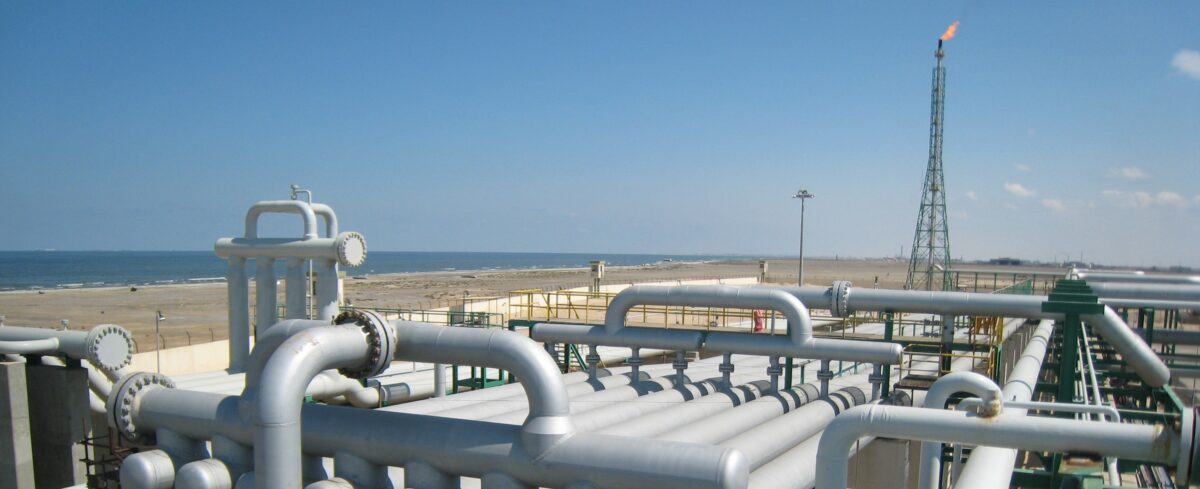
As a process engineer, one of the delights(!) awaiting you will be the P&ID review. Either, you’ll have responsibility for checking or approving P&IDs on a project (major or minor) generated within your organisation or provided by a supplier.
It’s one of those things that process engineers are expected to pick up on the job, usually by some form of osmosis, rather than helpful mentoring!
There’s one overriding principle to apply:
Think through the functions being served by each piece of equipment and continually ask whether what’s represented on the P&ID can fulfil each function. And remember the modes of operation, startup, shutdown and maintenance.
So here’s a checklist of things to look for:
-
- Is the purpose of the P&ID issue clear from the description e.g. Issued for HAZOP, Approved for Design etc.?
- Are all the notes accurately and appropriately referenced?
- Is the layout clear so that each line can be easily followed and not mistaken?
- Is there continuity of line numbering across each P&ID interface?
- Are there sufficient vents and drains to allow equipment to be prepared for maintenance or reinstated afterwards?
- Locate the HP/LP interfaces and ensure there is protection in place – either an open path to a relief device or vent, or a locked valve.
- Ensure piping specification breaks are clearly identified and line numbering follows the correct convention.
- Are the major process variables measured and controlled appropriately?
- Do the isolations e.g. double block and bleed, comply with the isolation philosophy?
- Are control valves clearly marked with the failure position on loss of motive fluid?
- Do the failure modes of control valves present a hazard?
- Are pressure boundaries respected when shutdown valves close?
- Are there open paths to blowdown valves from all equipment within each blowdown segment, to avoid locked in inventory?
- Are inlet lines to relief valves at least as large, if not larger than the inlet dimension?
- Ensure pressure relief paths are open.
- Are isolation valves upstream of relief valves locked in the correct position?
- Are isolation valves downstream of relief valves locked open (if present) even on standby relief valves?
- Are the slopes shown on lines in the correct direction to allow liquids to drain and not accumulate in the wrong places?
- Is there appropriate heat tracing and insulation provided on lines/bridles for winterisation?
- Is there appropriate insulation provided for personnel protection?
- Is instrumentation located suitably to avoid measurement interference?
- Are vents and drains to atmosphere which should normally be in the closed position shown with blanks or plugs?
- Are piping and instrumentation connected to the correct nozzles on equipment?
- Ensure there is no duplication of tag numbers.